Annex 6: 22KV Switchgear Arrangement
📊 Switchgear Arrangement Diagram
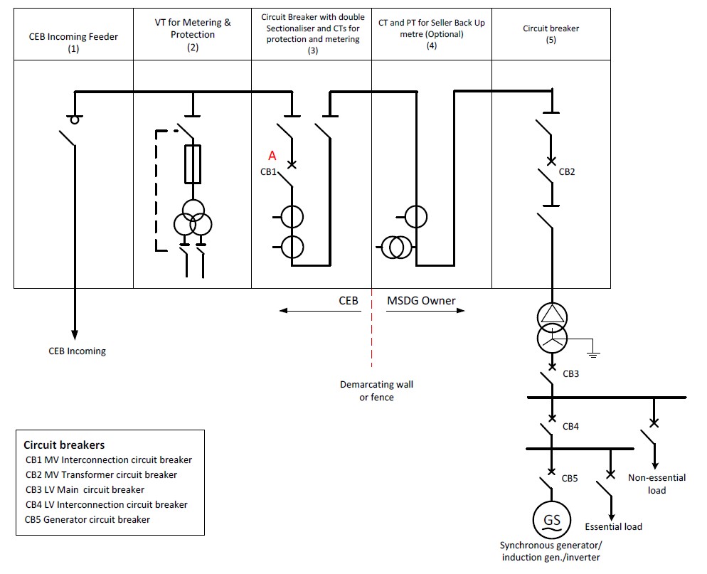
Expected Content: Complete 22kV switchgear arrangement showing CEB section, MSDG owner section, circuit breakers (CB1-CB5), metering points, and protection requirements.
Circuit Breaker Key:
- CB1: MV Interconnection circuit breaker (CEB side)
- CB2: MV Transformer circuit breaker (Client side)
- CB3: LV Main circuit breaker
- CB4: LV Interconnection circuit breaker
- CB5: Generator circuit breaker
Important Notes:
- A metallic barrier or demarcating wall/fence shall separate CEB and MSDG Owner sections
- Point A is the Point of Common Coupling (PCC) / Point of Delivery
- All protection relays and settings must comply with Chapter 3 requirements
- Switchgear must be metal-enclosed with appropriate IP rating
- For detailed electrical schematic, refer to Annex 8
Switchgear Layout Requirements
Physical Arrangement
The switchgears shall be arranged with CEB interconnection facilities and MSDG interconnection facilities demarcated by a metallic barrier. The complete 22kV switchboard includes both the CEB and the Client side, to be constructed, installed, tested and commissioned by the applicant. CEB will take ownership of its side after the guarantee period.
Equipment Specifications
All equipment shall meet the specifications detailed in:
- Section 3.3: MSDG High Voltage Switchgear requirements
- Section 3.4: MSDG Interconnection transformer specifications
- Section 3.6: Protection requirements for all circuit breakers
- Section 3.12: Metering requirements and accuracy
- Annex 7: Detailed technical specifications for HT Metering
Safety Features
The switchgear arrangement must incorporate:
- Appropriate interlocking mechanisms between circuit breakers
- Mechanical interlocking to prevent incorrect sequence of manoeuvres
- Safety interlocks as per IEC 62271-200
- Earth switches visible through cubicle windows
- Padlocking facilities on all disconnectors and earth switches
- MSDG warning labels at all required locations (see Section 3.14.4)
Metering Configuration
Two separate metering points are required:
- Import/Export Meter: Located at Point A (PCC), measures bidirectional energy flow between CEB network and MSDG installation
- Production Meter: Measures total generation output from the MSDG facility, installed by CEB in a dedicated metering cabin
Reference Documents
For complete details, refer to:
- Annex 7, Schedule A1: General switchgear specifications and cubicle arrangement
- Annex 8: Typical HV Switchgear Panel layouts with protection schemes
- Chapter 3, Section 3.3: Switchgear characteristics table