Annex 8: Typical High Voltage Switchgear Panel and Protection Guidelines
Note: The schematic diagrams below are typical installations. The actual protection and inter-tripping requirements may vary depending on the particular setup of the plant under consideration.
Annex 8(a): Typical High Voltage Switchgear Panel for Inverter-based Generation
📊 Figure 8(a): Inverter-Based MSDG Switchgear Panel
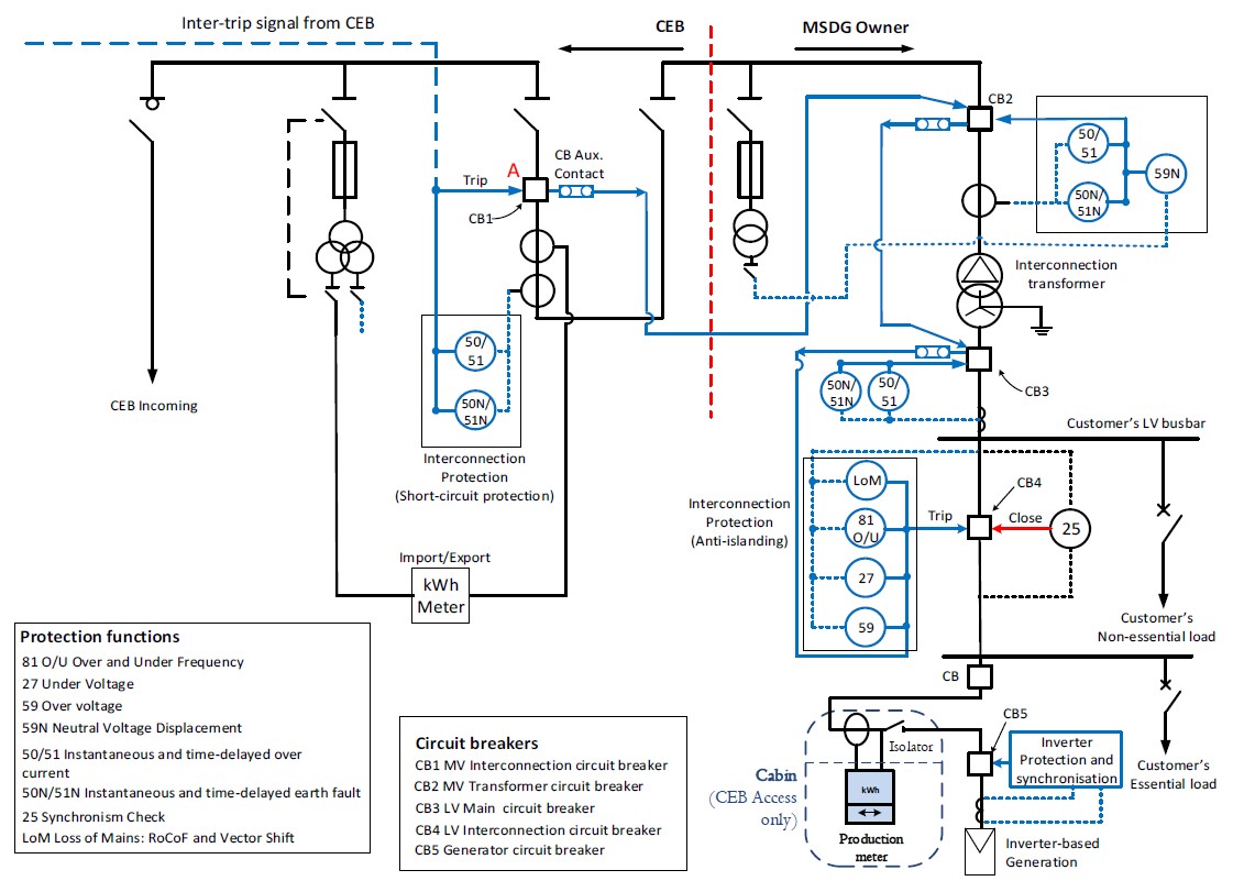
Expected Content: Complete schematic showing typical high voltage switchgear panel for inverter-based MSDG installations, including circuit breakers (CB1-CB5), protection functions, metering points, and interconnection requirements.
Key Circuit Breakers:
- CB1: MV Interconnection circuit breaker (CEB side)
- CB2: MV Transformer circuit breaker (Client side)
- CB3: LV Main circuit breaker
- CB4: LV Interconnection circuit breaker
- CB5: Generator circuit breaker
Protection Coordination for Inverter-based Systems
- Anti-islanding protection on CB4 shall act to disconnect generation within 0.5 seconds of island formation
- Inverter built-in protection may be acceptable if compliant with Grid Code standards
- For MSDG ≥ 1 MW: Inter-tripping from CEB substation required (refer to Section 3.6.4)
- CB1 opens on CEB protection operation → inter-trips CB2 → cascades to CB4
- Synchronism check (25) required before closing CB4 onto energized busbar
Annex 8(b): Typical High Voltage Switchgear Panel for Synchronous and Induction Machine-based Generators
📊 Figure 8(b): Rotating Machine-Based MSDG Switchgear Panel
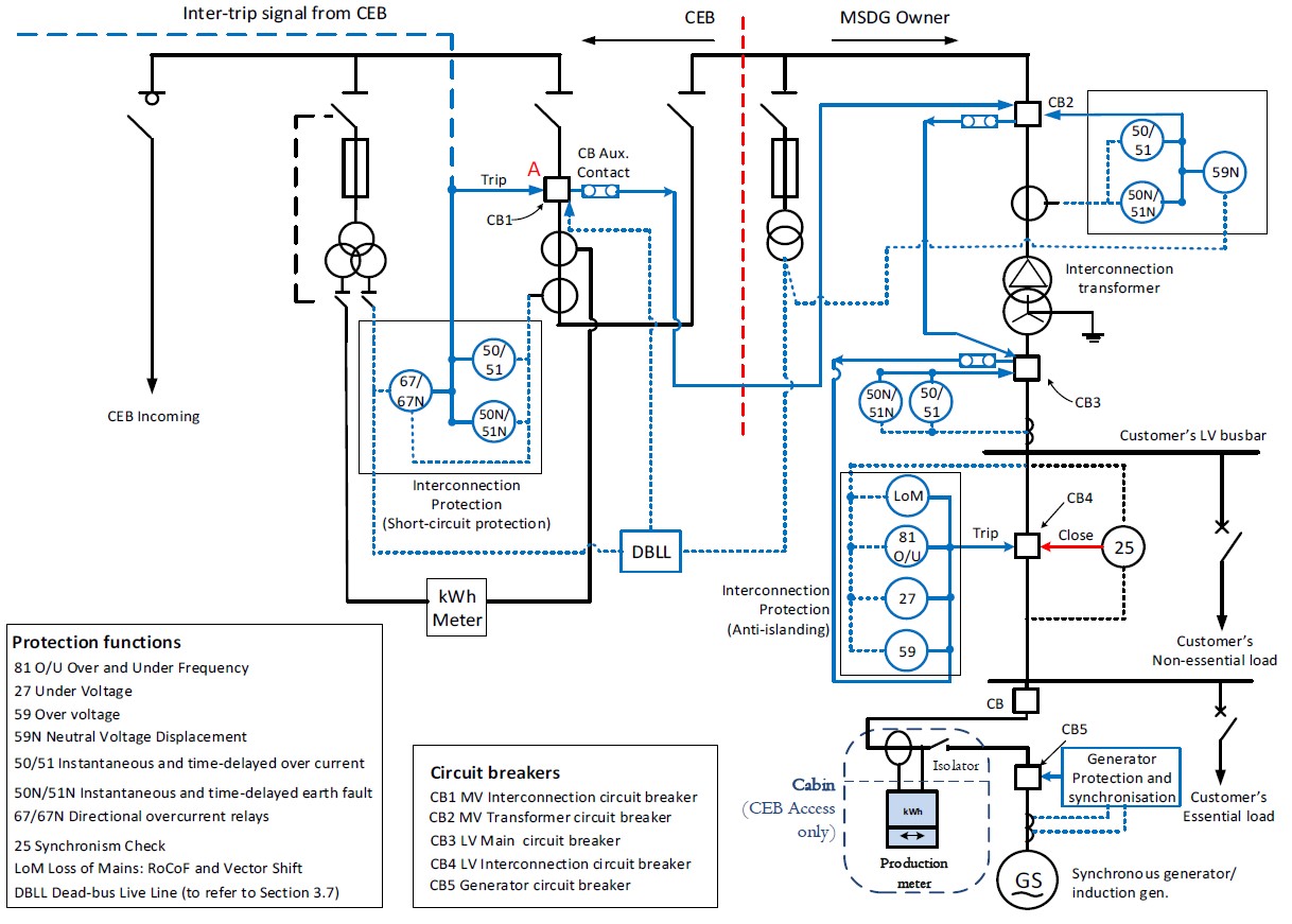
Expected Content: Complete schematic showing typical high voltage switchgear panel for synchronous and induction machine-based MSDG installations, including DBLL protection, check synchronizing requirements, directional protection, and mechanical interlocking.
Critical Differences from Inverter-based Systems:
- DBLL Protection: Required to prevent electrical closure of CB1 on energized client busbar
- Check Synchronizing: Mandatory on generator circuit breakers and any CB capable of paralleling
- Directional Protection: May be required on CB1 if settings discrimination not achieved
- Mechanical Interlocking: Must prevent CB1 mechanical closure while any client CB is closed
- Fault Contribution: Synchronous/induction machines contribute to fault current - settings must account for this
Notes for Both Configurations:
- The MSDG owner is responsible for providing the appropriate protection for his transformer and internal loads.
- The inter-trip between CEB substation and the MSDG plant is required for MSDG equal to or greater than 1 MW. Refer to clause 3.6.4.
- Under normal setup, NVD will be driven from PT on client side. Exceptionally, where it is practically not possible to install PTs on client side, the NVD (client side) may be driven by the PT protection core (CEB side), via a set of test block on CEB side. For new MSDG installations and Greenfield installations, PT on client side is mandatory.
- In cases where the MSDG system has been designed to operate in islanding mode, intertrip between CB2 and CB3 is required.
- For synchronous and induction machine-based generators (Section 3.7):
- A Dead Bus Live Line (DBLL) relay is required to prevent electrical and remote closure of CB1 on an energised busbar.
- A key interlock shall be provided between CB1 and all the client's outgoing 22 kV circuit breakers. This interlock shall prevent mechanical closure of CB1 as long as any of the client's outgoing 22 kV circuits breakers is closed.
- The onus lies on the MSDG owner to provide the required check-synchronism relay on circuit breakers where there exists the possibility of closing the generator live on the CEB system.
Protection Settings Summary
Reference to Protection Settings Tables:
- Table 4 (Section 3.6.2): NVD trip settings
- Table 5 (Section 3.6.3): Anti-islanding protection trip settings
- Overvoltage (U>> and U>)
- Undervoltage (U<)
- Overfrequency (f>): 52 Hz / 0.5 s
- Underfrequency (f<): 47 Hz / 3 s
- Loss of mains (LoM): 2.5 Hz/s (ROCOF) or 10° (Vector Shift) / 0.5 s
- Schedule A2 (Annex 7): Detailed protection relay specifications
Communication Requirements for MSDG ≥ 1 MW
For detailed communication system requirements, refer to:
- Section 3.11: Communication Requirements
- Annex 7, Schedule A3: Communication signal list
- Annex 9: Communication system diagrams and specifications